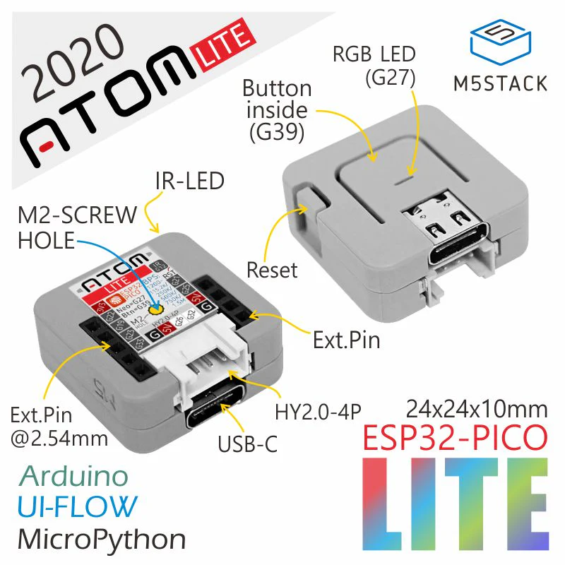
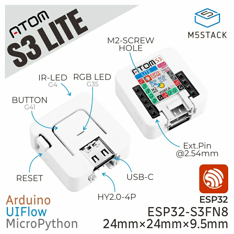
Atom-Lite & AtomS3-Lite Exercise: Setting up the Device
Connect the device to a USB port on your computer.
The USB port will power the device and enable serial communication.
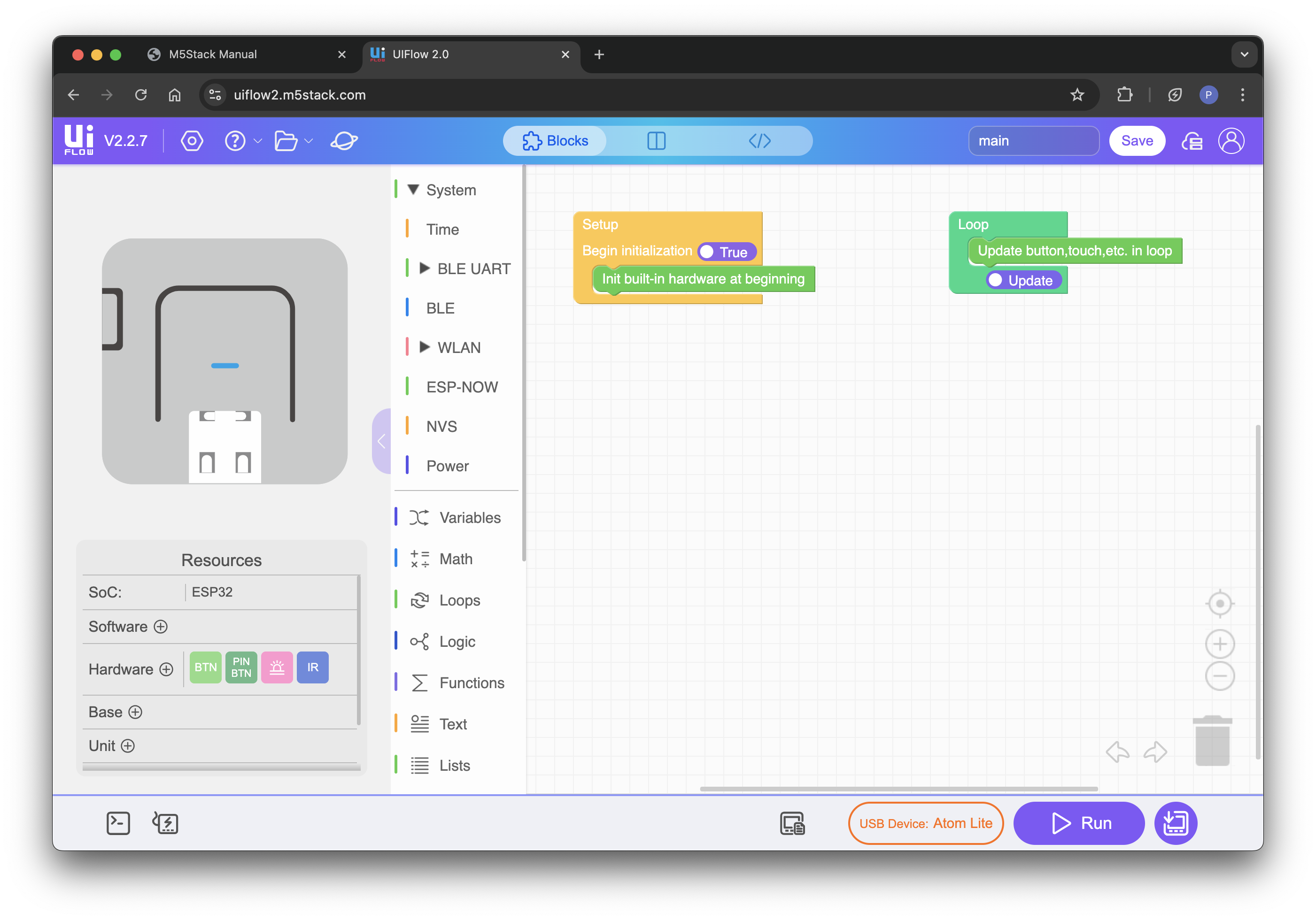
Open the UIFlow2 IDE 🔗
UIFlow 2 is a web-based graphical programming IDE that is easy for everyone to use,
with wireless/wired program push, program click and run, and no need to compile repeatedly.
Close both the UIFlow splashscreen and the project import screen.
We will use the wired (USB) mode, there is no need to create an account.
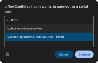
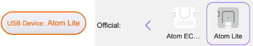
Select the apropriate device from the device list by clicking on the device button (bottom-right).
After selecting your device the code blocks for the built-in hardware will become available in IDE.
Let's do some coding!
Your first program: Color Clicker
In this exercise we will program the top button to change the color of the LED
and setup serial communication between the device and the IDE as we go.
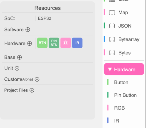
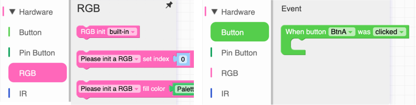
👁 Let's have a look at the code blocks for the built-in hardware (Button & RGB).
First, the RGB LED has to be initiated (drag the RGB init block in the Setup block):
The code in the Setup block will run once when the device starts up. ⚠ Never set the LED brightness > 70% to prevent the LED from getting too hot.
For the button we will need an event block
(drag the “When BtnA was clicked” anywhere on the canvas).
Drag the rgb fill color block in the event block.
You can change the color to your own preference:
Run the code on the device by clicking the “Run” button in the IDE (bottom-right).
⚠ Please avoid clicking the 'Download to Device' button (the firmware of the device has to be reconfigured if you do).
The Terminal will open, connect with your device and press “Play”.
If all went well your program will run.
Click the button on top of the device to see if the LED color changes.
The LED changes color but does not change back, (we didn't program it to...)
Let's make our program more interesting.
We want to randomise the RGB color of the LED.
We need to setup variables and a random function.
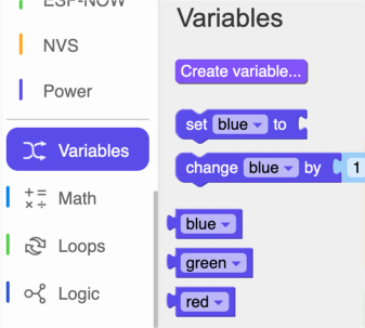
Create three variables: red, green and blue.
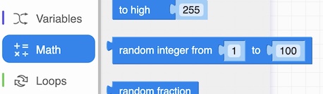
The random integer function can be found in the 'Math' code blocks.
Drag it into the canvas and change the values from 0 to 255.
Set up the Button event block to change the red, green and blue variables to a random integer from 0 - 255 and assign the variables to the RGB values of the Led:
💡 Tip: Double-clicking on a code block replicates it.
We also want to know the RGB values of the LED.
We need to read out the values of the red, green and blue variables over serial communication.
In micropython we use 'print' command.
You can find it in the 'Text' blocks section.
Drag the print block and the 'String Concatenation' block into the Canvas.
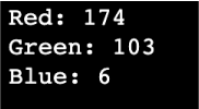
Set up the Button event as follows and run the program.
Test your program by clicking the top button and read out the values in the webterminal.
🎆
Now we have succesfully programmed the built-in hardware of our device we can take a look at some additional hardware.
You can connect Units (sensors) and Bases to your device to extend it's functionality.


 ⚠ Please avoid clicking the 'Download to Device' button (the firmware of the device has to be reconfigured if you do).